In robot vision, calibration was never a one-time job. It had to be repeated every time part height changed. AimFactoryCore replaces that repetition with calculation.
Why a change in height throws off the pick
The camera looks down and converts pixels to millimeters. That conversion is exact only at the height where calibration was done. If a part sits higher or lower, the distance between camera and part changes, and the same pixel now points to a different millimeter.
The error is small at the center of the field of view and grows toward the edges. So when parts of different heights are picked with one calibration, the ones at the edge of the pick area are the first to drift.
Until now the answer was to calibrate at each height and keep several sets of data. The more part types, the more sets.
How AimFactoryCore handles it
In the hardware step of the calibration window, you enter the camera’s measured working distance. With that value the software computes the change in scale with height using a projection formula. Cases that include rotation are handled by the same formula, so there is no need to measure a separate compensation coefficient for each axis.
Product height is stored per camera inside the recipe. Change the part, and the recipe changes, and the height changes with it. The product height card in the Point Tool screen shows this value as is; editing is only done in the calibration window, to keep the value from being changed by accident during production.
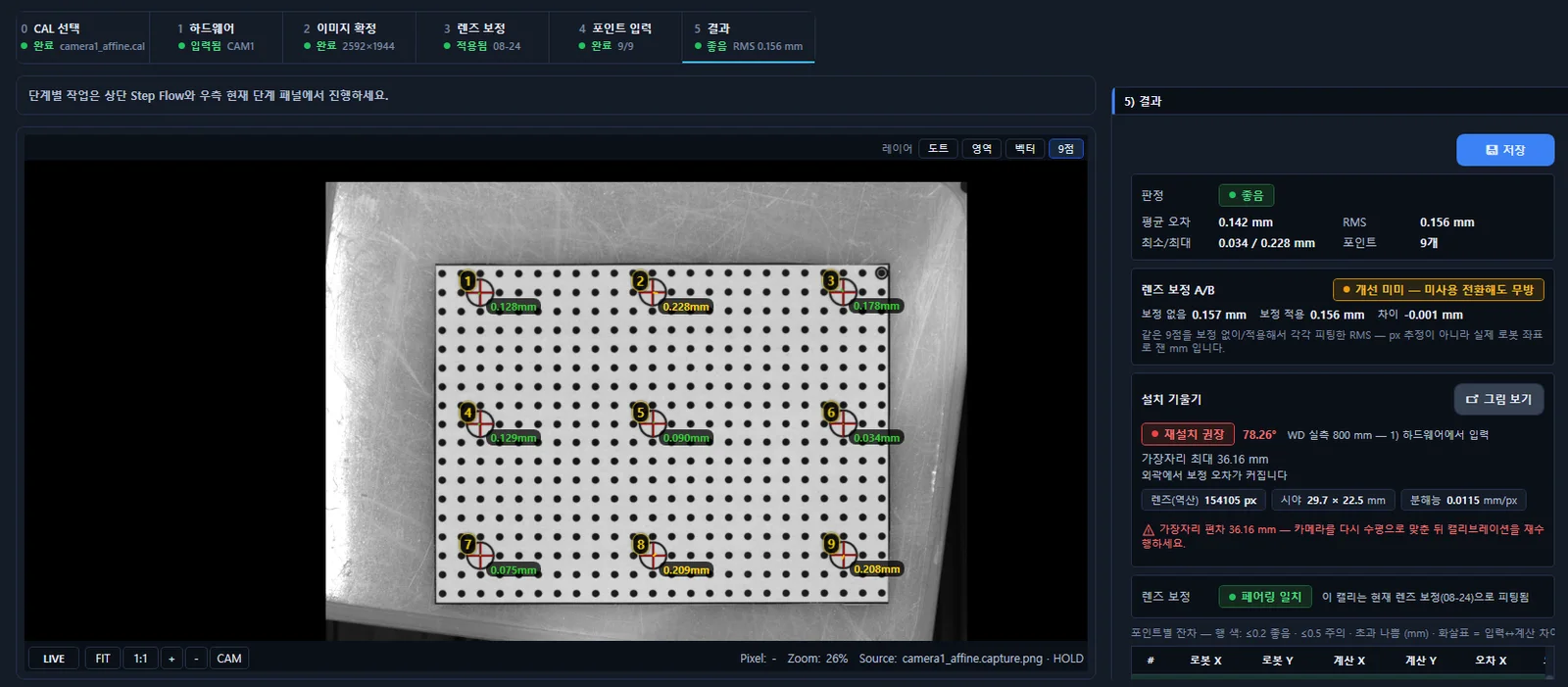
Results are checked against what the screen reports. The calibration result step shows an RMS value with a good, caution, or poor rating, and the mean, minimum, and maximum errors in millimeters. If the camera is installed at a tilt that would inflate edge error, a reinstall warning appears on the same screen.
Lens distortion is removed first
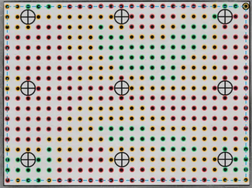
Lens correction comes before height compensation. Capture a dot board and the software detects the dots automatically, marks each dot’s state in color, and places crosshairs on the nine points.
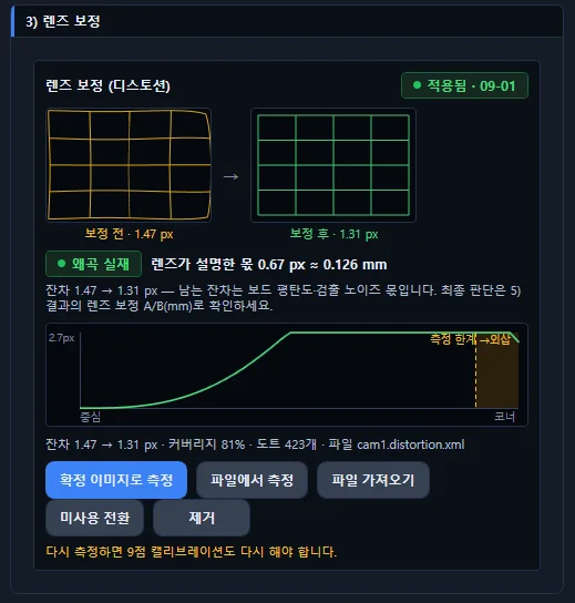
The lens correction panel shows the grid before and after correction, the residual, coverage, and the number of detected dots, with the residual expressed in millimeters as well as pixels. The final call is made in the result step: the same nine points are fitted once without correction and once with it, and the two RMS values are compared. For the lens in the screenshot the difference was 0.001 mm, so the software rated the improvement negligible and noted that correction can be switched off. A correction that is not needed is reported as not needed.
A wrongly entered point is pointed out on screen
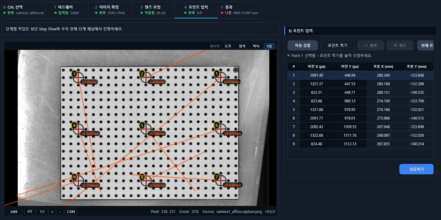
Enter one of the nine points incorrectly and the rating turns poor, with the error next to each point in millimeters. You can see which point is off and by how much, so only that point needs to be re-taken. This check is possible because the reference stays in robot coordinates.
What is missing is reported as missing
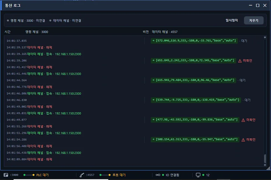
If the calibration data lacks camera information, lens correction, or working distance, it is flagged as unconfirmed and the missing items are listed. If the working distance is absent, the screen states that height compensation and tilt calculation are not available. This is meant to reduce unexplained drift at sites that migrated older data.
Where it matters
- Mixed-model lines that alternate between parts of different heights
- Feeding setups with a wide field of view that use the edge of the pick area
- Sites that used to wait for a calibration engineer every time the part changed
Precision does not come from one place
Height compensation is one of several stages where AimFactoryCore removes error. It works together with registration referenced to the robot’s absolute coordinates, lens distortion correction, tool calibration that compensates per angle for a mechanically offset tool, and pick offsets entered in vision without opening the robot program. That structure is covered separately on the technology page.