Calibration
So the spot you find is the spot you pick
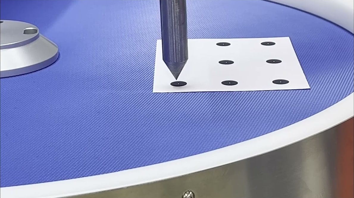
Turning the pixels the camera sees into the millimetres the robot moves. Where the reference sits, and where misalignment gets corrected, is what decides accuracy.
01
The robot is the reference
We do not create a new reference frame on a jig. The jig is removed once calibration is done, and after that there is no way to check that reference again. If it was built even slightly off-angle, the means to find that out disappears with it.
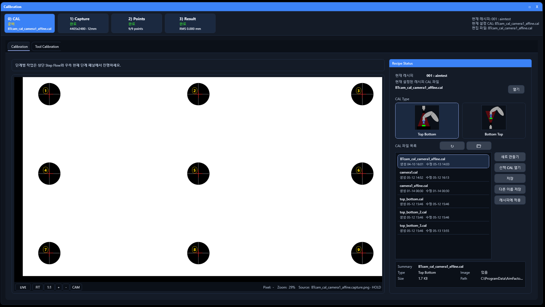
AIM aligns the camera to the absolute coordinates the robot reports. Because the reference stays inside the robot, when something drifts later you can trace where it started drifting. The alignment result is not a promised figure but the value the screen shows — at the result step, the mean, minimum and maximum error appear in mm.
02
Offsets are entered in vision
When you want to shift the pick position slightly, you do not open the robot program.
Entered on the robot
Every change means editing the robot program. Whether you go in through the pendant or install the robot maker's software on a PC, it is hard to find later where the changed value went.
Entered in vision
Tool values, pick height, offsets and place pose are all inside the recipe. Edit them on the PC screen; switch products and those values switch with it.
03
As far as the tool is off, compensated at every angle
If the gripper is mechanically biased to one side, or is not concentric after assembly, the pick position changes with the angle every time the robot rotates. It is a mechanical error the camera cannot see.
The robot is rotated over one fixed point, the resulting coordinates are circle-fitted to compute the tool centre, and the radial deviation is plotted in ±mm. Once these values are registered, the software computes a pick coordinate matching the detected part orientation and sends it to the robot. The existing tool settings inside the robot are left as they are.
04
A different height does not mean recalibrating
When the distance between camera and part changes, the same pixel points to a different mm — and the deviation grows towards the edge of the field of view. Run products of different heights together in production and that deviation becomes pick error as it is.
Enter the product height and the software recomputes against the working distance, so parts at the outer edge of the pick area are picked with the same accuracy. The height is stored in the recipe, so changing the product changes the height with it. There is no need to keep separate calibration data per height.
05
Results stay as numbers and pictures
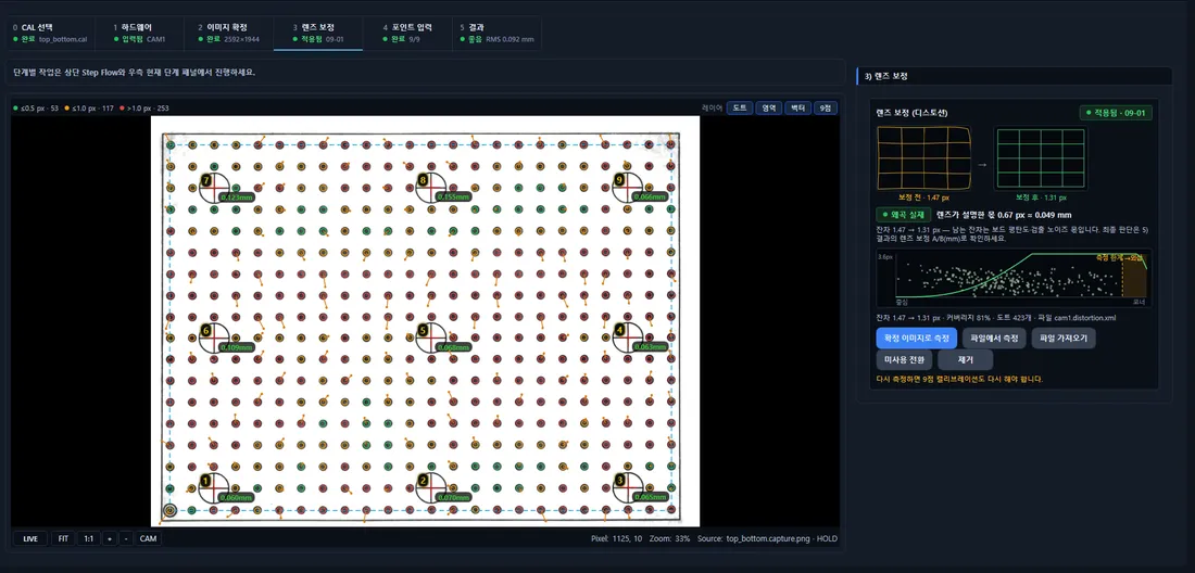
Whether it fits well is not judged by feel. The error at each point, the lens distortion and the as-installed relationship each remain on screen.
Products
That was the principle. To bring it in as a product
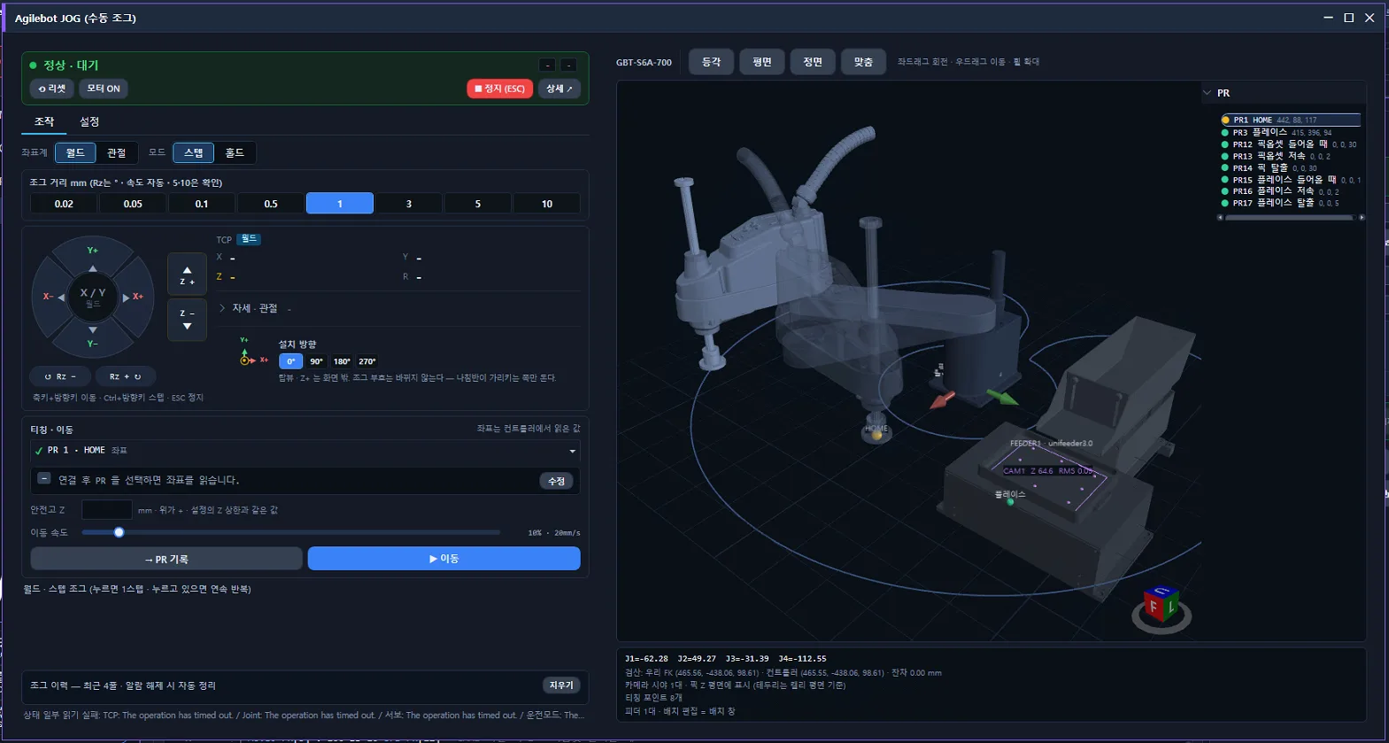
What actually runs the alignment and compensation above is AimFactoryCore. Calibration results and tool deviation are checked inside that screen.
Want to see how well it fits your current robot and parts?
Tell us the robot you use, the type of parts and the gripper shape, and we will review the alignment conditions with you.