
Robot Vision Automation
What it takes for vision to move a robot
Coordinate conversion, communication and inspection have to be tied into one structure before pick automation works.
01
Robot vision and inspection vision are different
Inspection vision outputs pass/fail (1/0); robot vision produces X / Y / θ coordinates the robot can use right away. Connect them without understanding this difference and the robot does not know where to go.
The difference between the two in detail →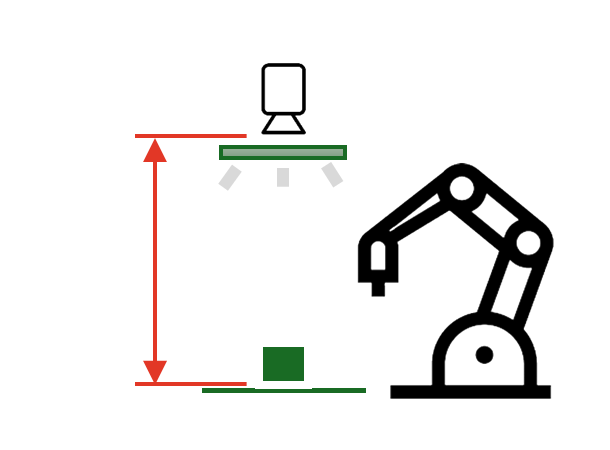
650mm+
Shooting distance that clears the robot arm
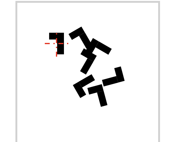
Up to 6 picks
Coordinates for several parts from one capture
X / Y / θ
Robot coordinates, not OK/NG
02
Calibration — aligning camera and robot coordinates
The coordinates the camera sees and the coordinates the robot moves in are different from the start. Unless 9-point calibration brings the two together, picks miss no matter how good the recognition rate is.
Tool correction and product height too — Calibration →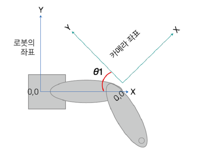
03
Coordinate transfer — TCP/IP and IO communication
Pick coordinates are sent directly over a TCP/IP socket, or trigger and done are exchanged as digital IO signals. Many brands — ABB, UR, Hyundai Robotics and more — support this standard communication.
Robot integration in detail →TCP/IP communication flow
Send trigger
Robot → vision PC: capture and recognition request
Wait for the response
Wait until the vision PC sends the CSV string
Parse the received data
OK/NG
Result
X
Position
Y
Position
RZ
Angle
n
Count
Confirm the robot move condition
04
Coordinate transfer — vendor-specific protocols
Some robots use a manufacturer's own protocol, such as FANUC (PCDK) or YASKAWA (Motocom/MotoPlus). AIM integrates these vendor protocols too, with dedicated handling.
Robot vision automation in detail →
AGILEBOT
05
Template matching and recognition performance
A reference image (template) is compared with the captured image to find position and rotation angle — about 0.5 s including a full-frame 2592×1944 search and decision (capture and robot transfer excluded). Performance comes from lighting, lens and capture environment before the algorithm, so per-part conditions are saved and kept as a Recipe.
See AimFactoryCore →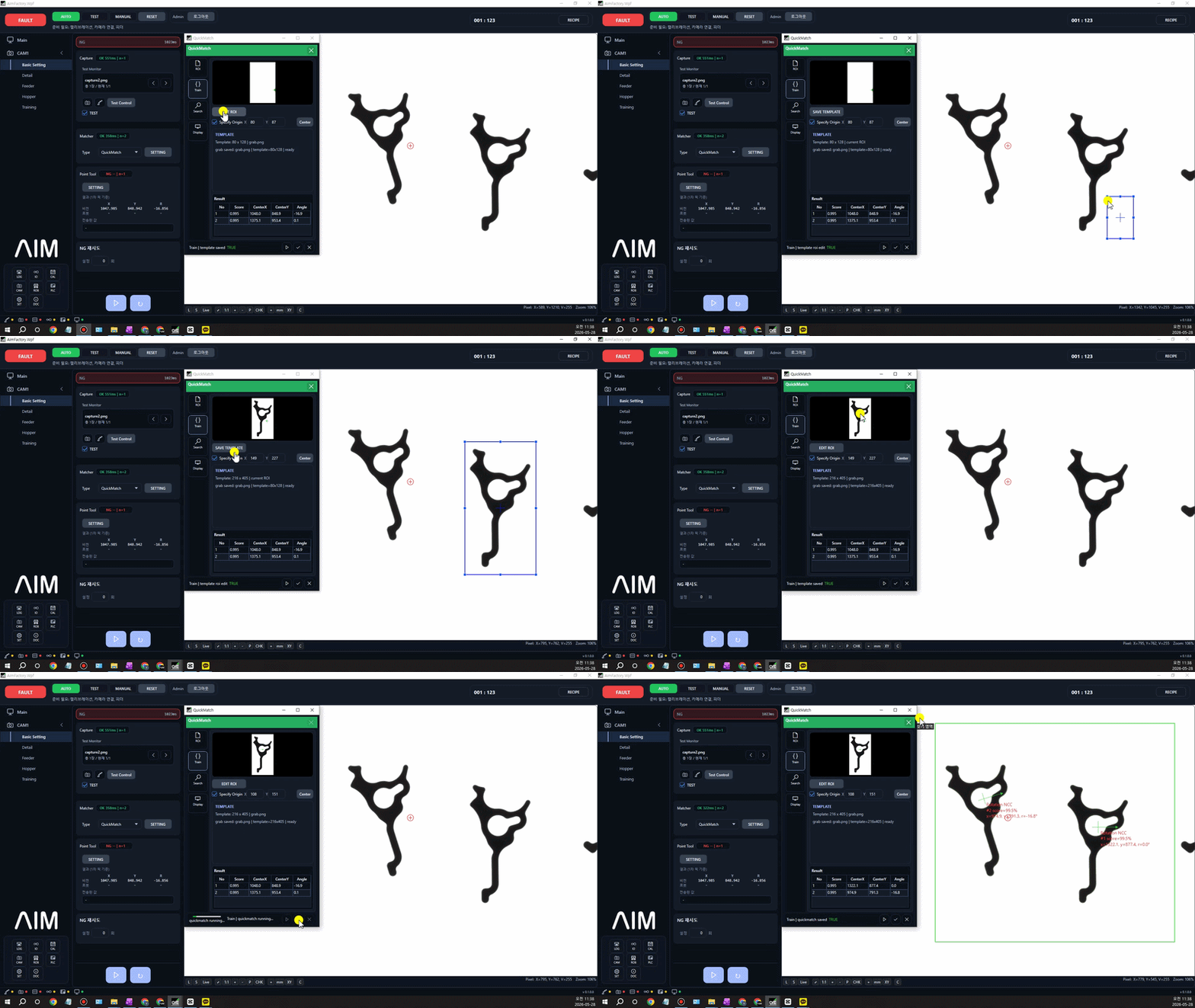
① Matching setup
Register the reference image (template) and save the ROI, lighting and exposure conditions as a Recipe.
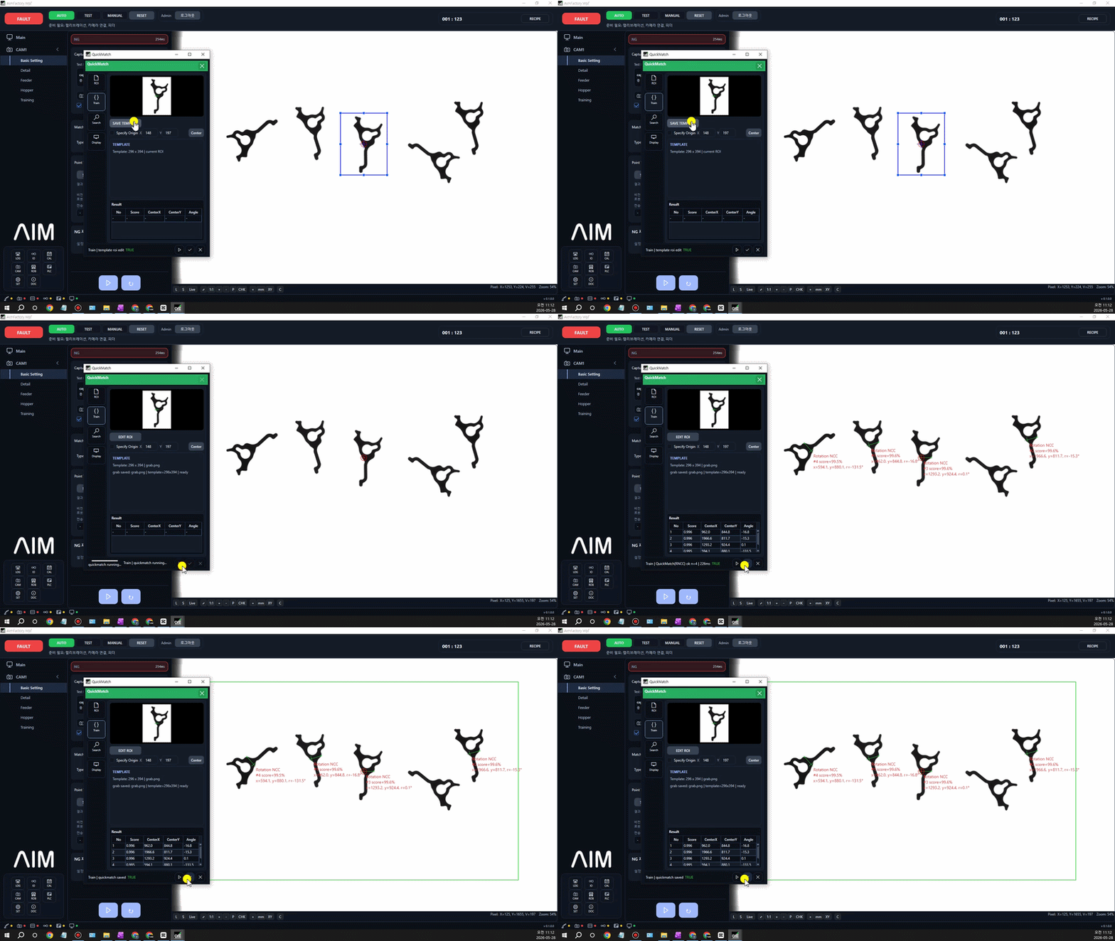
② Recognition result
Part position and rotation angle are detected in real time and the coordinates are passed to the robot.
06
The inspections robot vision needs
In pick automation, vision does more than "find the position." It also inspects whether the part was gripped properly, whether the orientation is right, and whether it can move on to the next process.
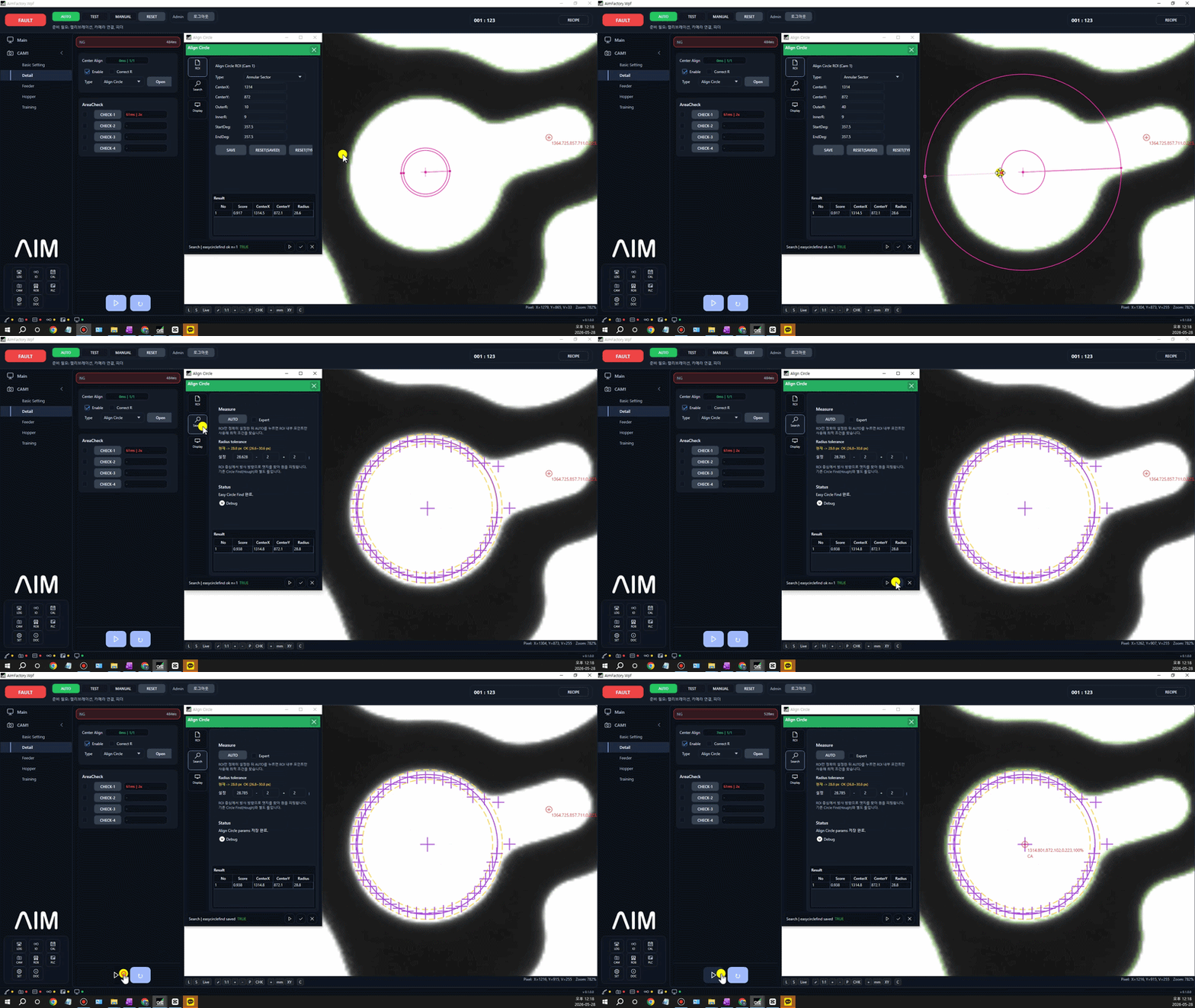
Circle center correction
Checks the part's front/back and orientation before the pick and filters out orientation defects.
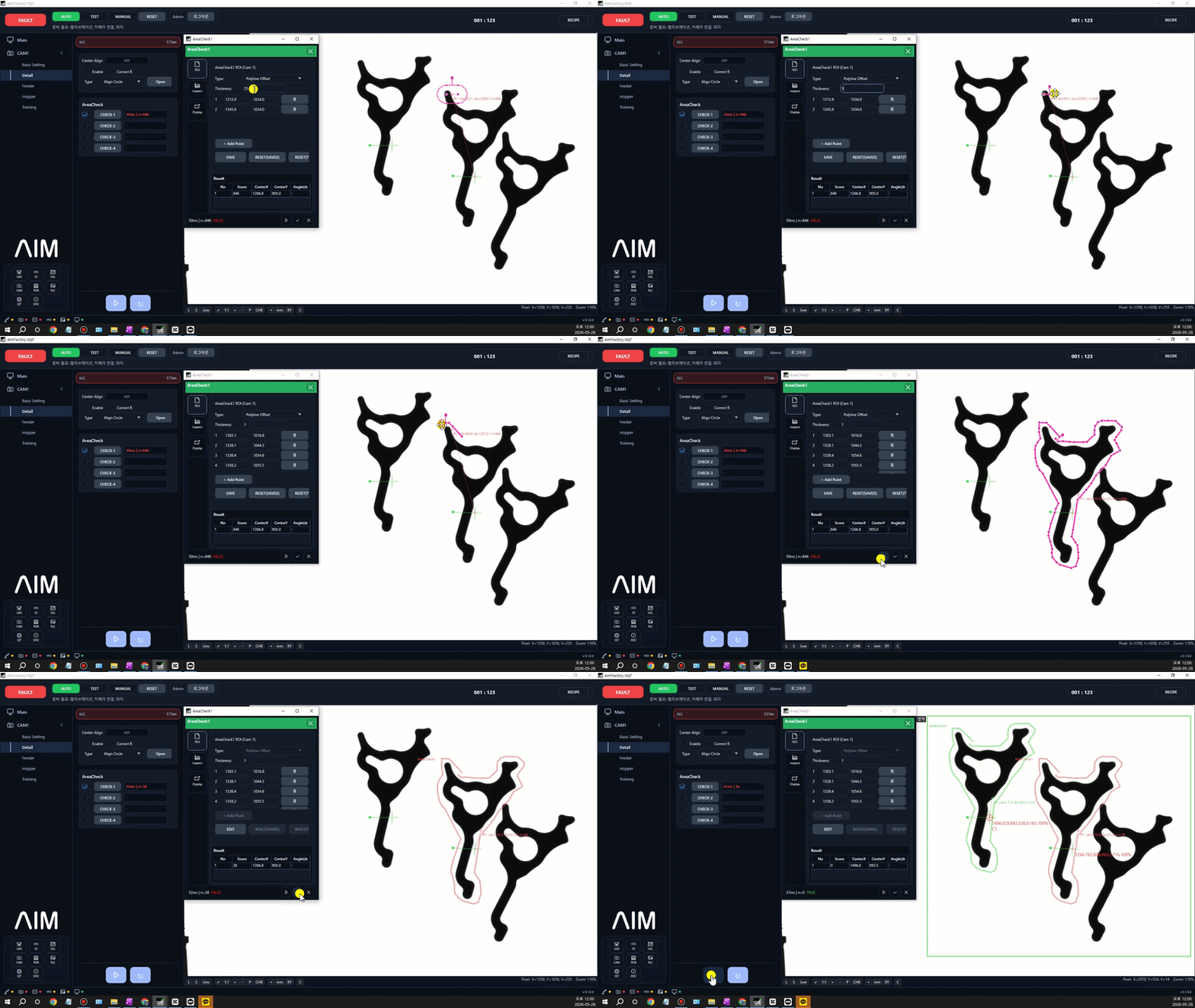
Overlap inspection
Detects overlapping parts so that only cleanly separated parts are selected as pick targets.
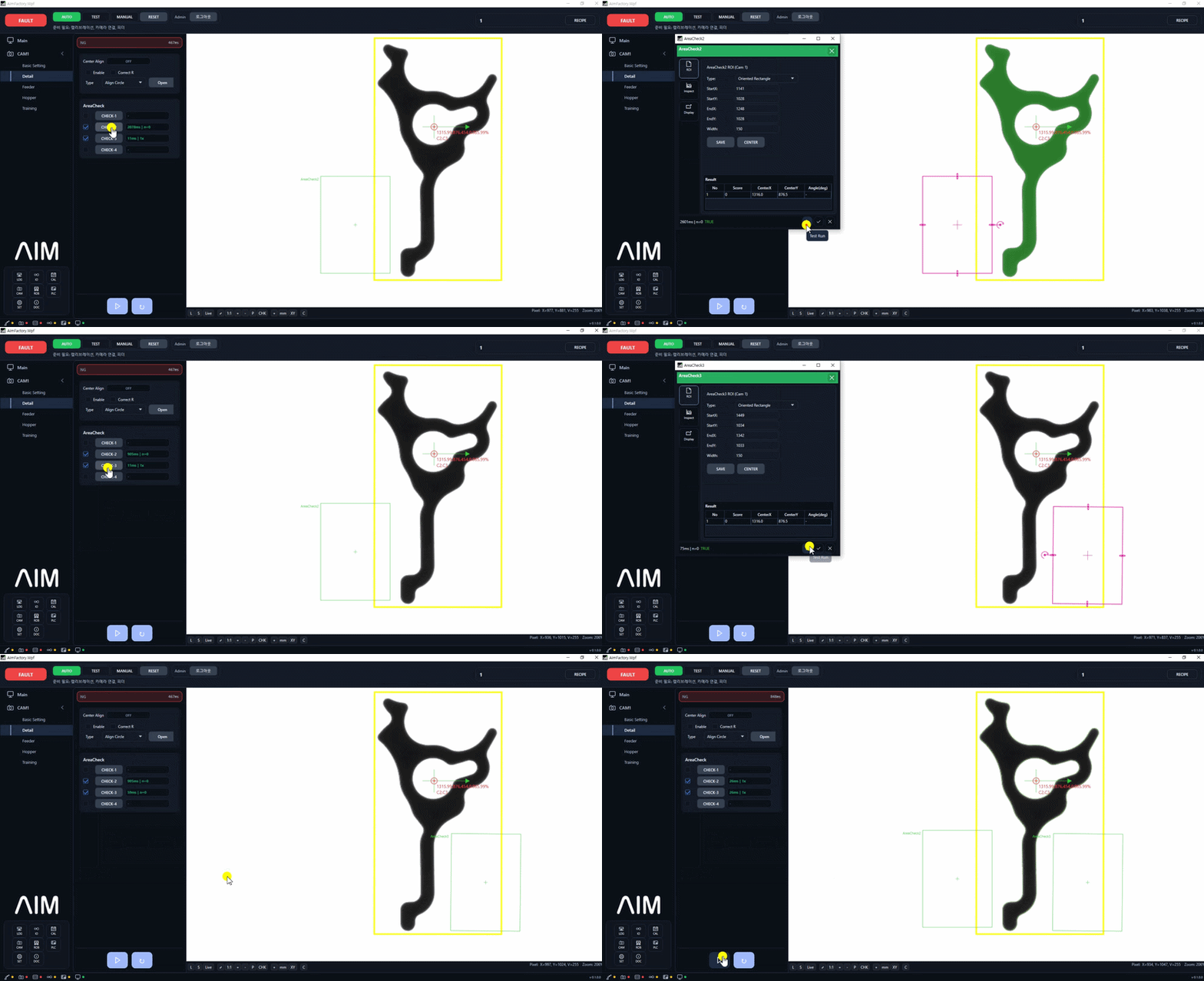
Gripper inspection
Checks the grip state after the pick and filters out failures and misalignment before the next process.
Case studies
Cases applied on real parts, robots and lines.

Electronic component manufacturing · Undisclosed
4×6 mm Silicone Parts a Vibratory Feeder Couldn't Handle, Auto-Inserted into Trays at 0% Defects
Read the case →

Electronic component manufacturing · IAI Robotics
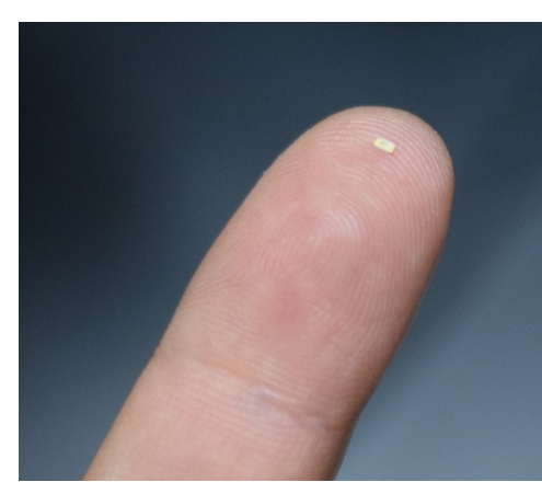
0.3 mm SMD Parts, Reel Taping Automated with ±0.05 mm Pick-and-Insert Error
Read the case →
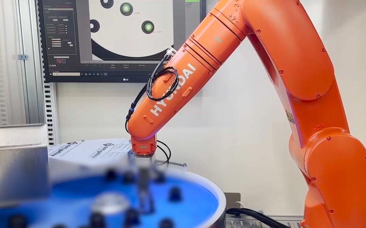
Automotive parts · Hyundai Robotics (joint verification)
Variant Changeover Under 5 Minutes, Pick Alignment ±0.2 mm — Hyundai Robotics HH7 Flexible Feeding
Read the case →
Products
That is the principle. To bring it in as a product
What actually runs the recognition, coordinate alignment and robot integration above is AimFactoryCore. A vision-only configuration is also possible.
Want to check whether it works with your parts and robot?
Tell us the robot you use, your part types and process conditions, and we will review a suitable configuration with you. Vision software alone can also be introduced on its own.