Case Study · Electronic component manufacturing

4×6 mm Silicone Parts a Vibratory Feeder Couldn't Handle, Auto-Inserted into Trays at 0% Defects

4×6 mm transparent silicone parts that a bowl feeder could not feed at all because of their elasticity and surface tension were auto-inserted at 30–40 pcs/min with 0% defects using the existing trays, replacing the manual work of six operators across two day/night shifts.

Defect rate Tray insertion process
0%
Feed and insertion rate 4×6 mm silicone parts
30–40 pcs/min
Vision coordinate correction This case configuration
±0.05 mm
Manual labor replaced Two day/night shifts
6 operators
4×6 mm Silicone Parts a Vibratory Feeder Couldn't Handle, Auto-Inserted into Trays at 0% Defects

What and how

Configuration of this case

Part
Transparent silicone part (elastomer)
Size
4 × 6 mm
Process
Tray insertion (incl. front/back sorting and flipping)
Feeder · Vision
AIVE flexible feeder + RoboEYE vision
Industry
Electronic component manufacturing
4×6 mm Silicone Parts a Vibratory Feeder Couldn't Handle, Auto-Inserted into Trays at 0% Defects — part and detection view

Challenge

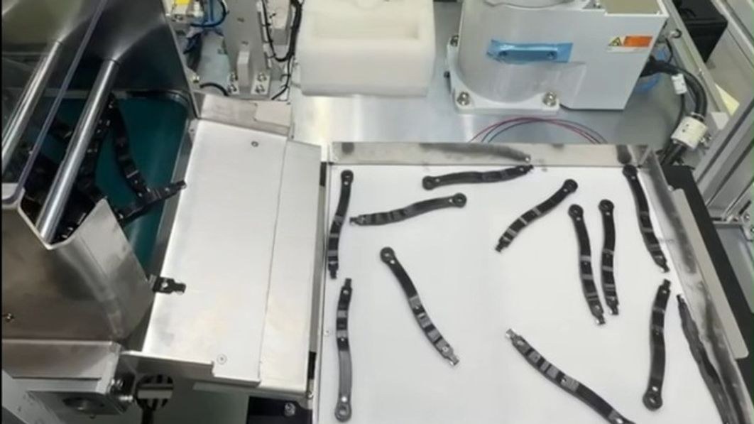
The part would not align on a bowl feeder track, so feeding automation itself was blocked

The 4×6 mm transparent silicone part has high elasticity and surface tension, so a bowl (vibratory) feeder could not feed it. Because it was hard to tell which way the groove faced, front/back sorting and flipping were difficult as well. The work was therefore done by hand, with operators pressing parts one by one into each tray pocket — six people across two day/night shifts. Operator fatigue and quality variation were direct process risks.

Solution

Spread and flip the parts, read the groove direction, and insert into the existing trays

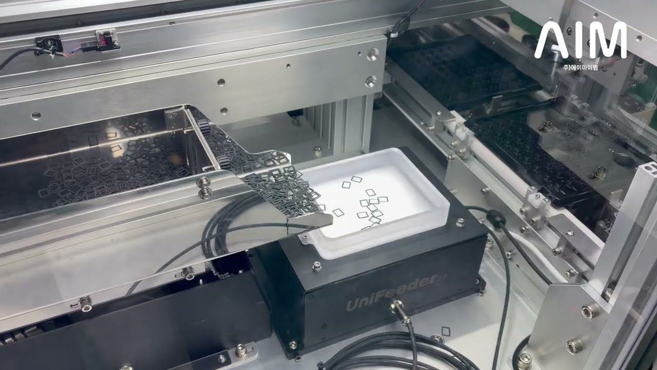
The AIVE flexible feeder handles the stretch-and-flip sequence that spreads the parts on a flat surface and turns them over. Amplitude, frequency and transfer pattern were tuned to this part to reduce overlap and tangling.

4×6 mm silicone parts spread on the AIVE flexible feeder

RoboEYE vision recognizes the groove direction to judge front from back and corrects the insertion coordinates to ±0.05 mm. Because the tray tolerance is tight, the insertion path was computed separately from these correction values.

  • Groove-direction recognition judges front from back; flipped parts are returned by the feeder sequence
  • The existing tight-tolerance trays were used as-is, with no mold or specification change
  • A dual tray carrier keeps feeding going while trays are being changed

Robot inserting a silicone part into a tight-tolerance tray pocket

Results

A process six people did by hand now runs on the machine without stopping

  • 0% defect rate — tray insertion process
  • 0% production stoppage — dual-tray continuous operation
  • 30–40 pcs/min — feed and insertion rate for 4×6 mm silicone parts
  • Replaced manual insertion by six operators across two day/night shifts
  • Applied without changing the existing tray mold or specification
FAQ

Frequently asked about this case

How do you feed parts that a vibratory (bowl) feeder cannot handle?

The 4×6 mm transparent silicone parts in this case would not align on a bowl feeder track because of their elasticity and surface tension. The AIVE flexible feeder spread the parts on a flat surface, and the vision system located each part's position and orientation and passed the coordinates to the robot.

Can sticky, elastic parts like silicone or rubber be fed automatically?

In this case the amplitude, frequency and transfer pattern were tuned to the part to reduce overlap and tangling, and a stretch-and-flip sequence sorted out mixed front/back orientations. Conditions differ from part to part, though, so verification with the actual part is needed.

Can the vision system tell the front from the back (groove direction) of the part?

In this case, RoboEYE vision recognized the direction of the part's groove to judge front from back. Flipped parts were turned over by the feeder's flip sequence.

Can we keep using the trays we already have?

This case used the existing tight-tolerance trays as-is, with no mold or specification change. The ±0.05 mm correction values computed by the vision system were used to generate the insertion path and handle the tolerance.

Does feeding continue while trays are being changed?

A dual tray carrier was configured so feeding does not stop while trays are swapped. In this case the line ran with 0% production stoppage.